Control Amplifier.
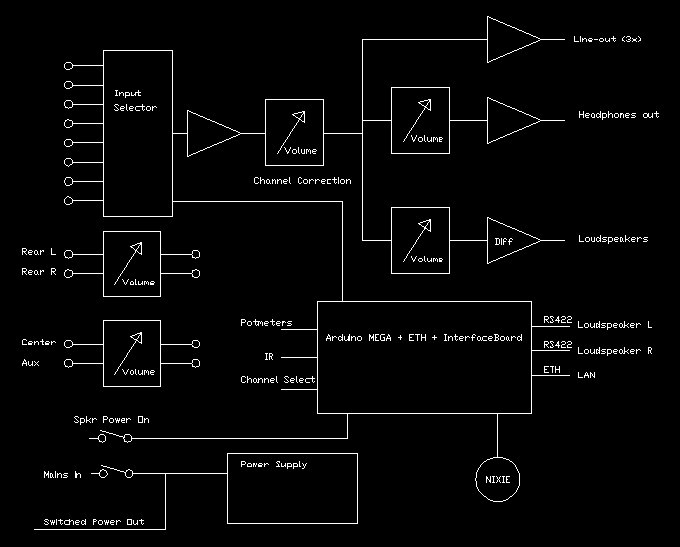
Block Diagram.
One of 8 stereo inputs can be selected. Depending on the channel a volume correction is applied to match different output levels of the audio sources.
After this correction the signal goes to the line drivers for music elsewhere in the house, via a volume control to the headphone jack and via another volume control to the loudspeakers.
4 extra channels allow surround-sound signals to be volume-controlled in sync with the loudspeaker volume.
The whole thing is controlled by an Arduino Mega and an interface board. The Mega also has an ETHernet shield to allow communication with the Configuration Tool.
For a description of the software see the Software page and / or the Messages page.
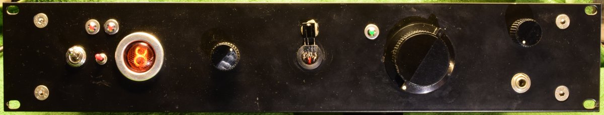
Front view. The amplifier is housed in a 2U high 19" cabinet.
From left-to-right:
- Mains power switch. Also switches power to other equipment in my audio rack.
- Switch for power to the speakers.
- Red led's give error status from the power amplifiers.
- Nixie tube indicating the selected input channel.
- Channel selector. A quadrature switch, because channel selection can also be done over IR.
- IR sensor. (needs cosmetic improvement)
- Green led indicating activity on the volume pots. Flashes during Mute.
- Volume control for the speakers. It is a motorized pot because volume control can also be done over IR.
- Volume control for the headphone output.
- Headphone output.
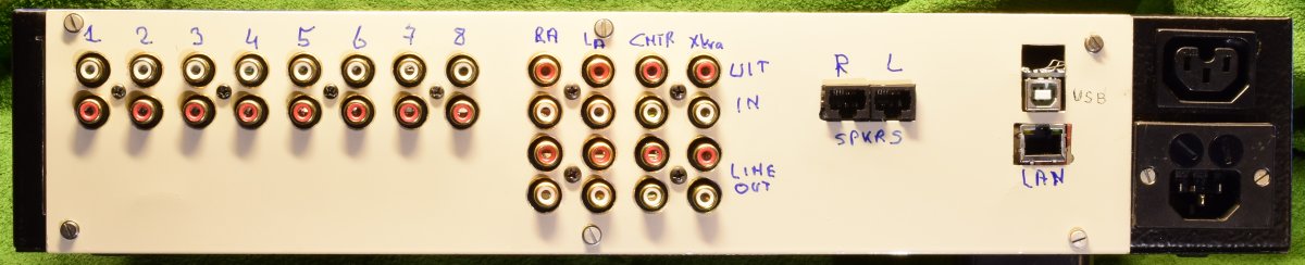
Backside view.
From left-to-right:
- 8 stereo input channels.
- 4 inputs and outputs for volume control of surround signals, synchonized with the speaker volume setting.
- 4 low impedance line outputs for music elsewhere in the house.
- 2 RJ45 connectors to the loudspeakers.
- USB input for programming the Arduino processor.
- RJ45 connector to the local area network.
- Switched mains output to other equipment in the audio rack.
- Mains input.
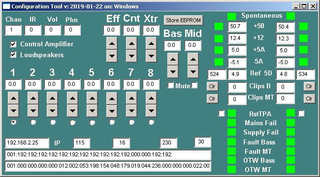
Screenshot of the Configuration Tool.
The Configuration Tool is a software program that runs on a PC or Laptop. It is used to set the relative sensitivities of the 8 audio inputs and the effect volume controls, and the matching of Bass en Midrange to the Tweeters. Besides that it has some diagnostic features.
Top left we see the actual settings of the input channel selector, the latest code from the IR remote and the potmeter settings (8 bit ADC-values) for the speakers and the headphone.
Check boxes to enable communication with the Control Amplifier and the Loudspeakers.
Relative channel sensitivity settings in dB, with up-down buttons and a radio button indicating which channel is selected.
At the bottom some diagnostic info from the messages exchanged with the Control Amplifier.
Just right of the center we see controls to adjust the volume of the Bass and Midrange channels in the loudspeakers.
To the right diagnostic information from the loudspeakers. Supply voltages and error status.
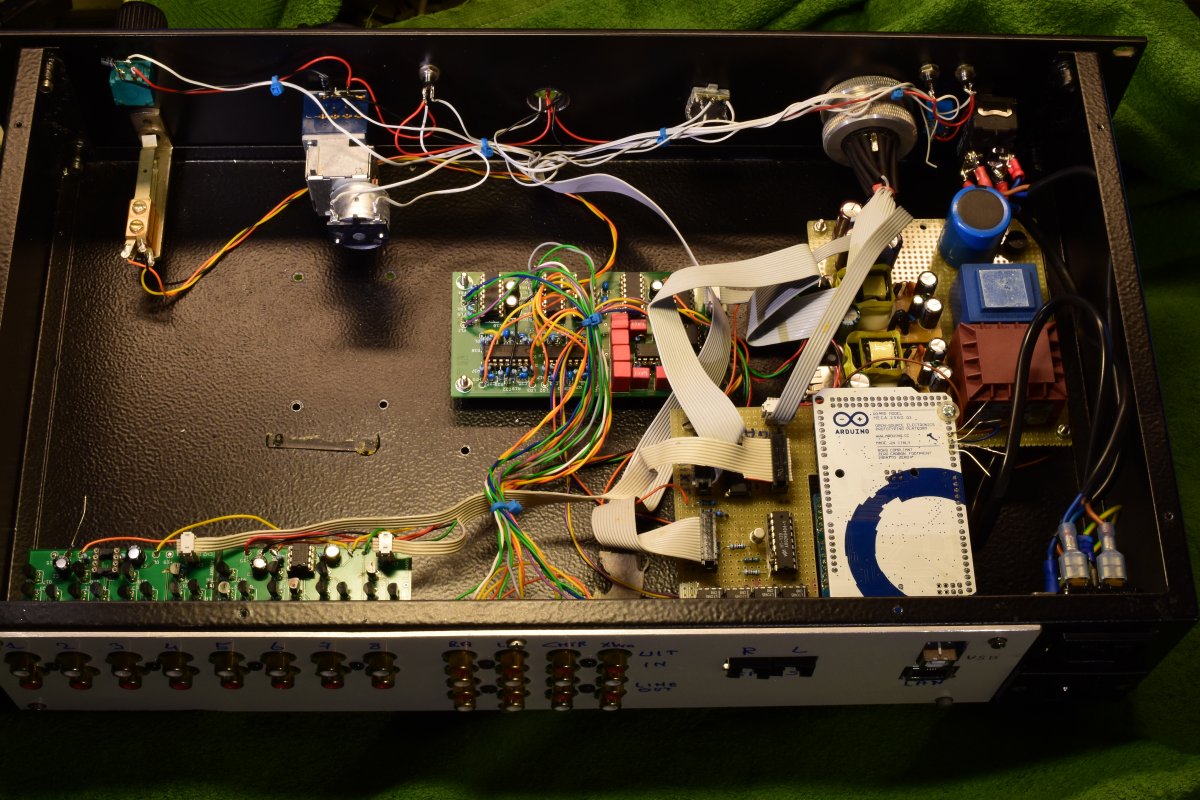
Inside view in the direction of the front panel.
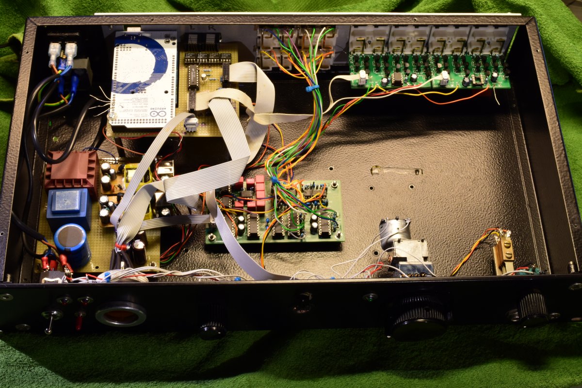
Inside view in the direction of the backpanel.
Upper right: 2 selector boards for the 8 input channels.
Upper mid: Connectors for surround in / out and the line outputs.
Upper left: Arduino MEGA and interface shield. The ETHernet shield sits below the Arduino and is not visible in this picture.
Upper far left: Mains in- and output.
Center: The gain control PCB with the PGA2311 IC's.
Left: power supplies.
Bottom: the front panel controls.
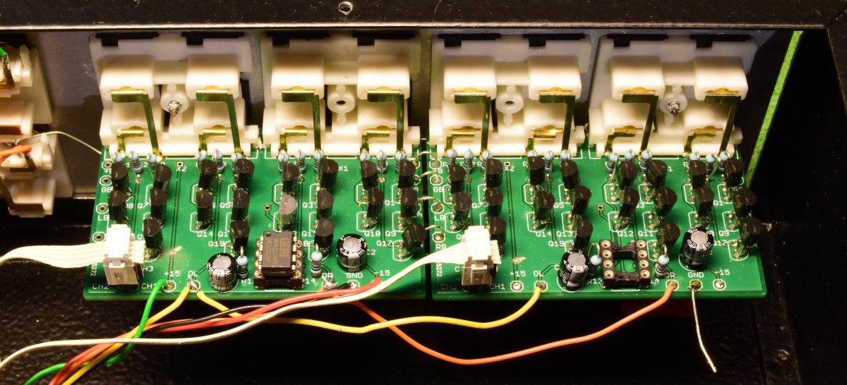
Selector PCB's in close-up.
Download the schema in PDF, the board in PDF and / or the zipped Eagle files.
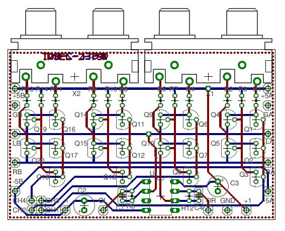
Selector PCB.
This board provides input selection for 4 stereo channels. Two of these boards in tandem provide the 8 input channels in my system.
Note that the board has a GND plane on the top side. (The dotted line).
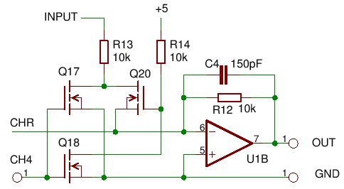
Principle of the operation (subset of the schema, right channel of X2B )
The right channel signal enters through R13. If the channel is selected (CH4=low, Q18=off, Q20=on) the signal goes through Q20 to the collector line CHR.
Compared with the 10 kOhm of R13 the Rd-on of these fet's is so low that the non-linearity of it will not produce noticeable distortion. More over, the voltage between drain and source is very, very small.
The collection line is on the inverting input of the opamp, being virtual GND. The non-linear input capacitance of the opamp will not produce distorsion because there is no noticeable signal voltage there. (even at 20 kHz the voltage gain of this opamp is over 300).
When deselected (CH4=high) Q17 short-circuits the input signal to GND, so there is only an extremely small signal on the drain of Q20 which will not produce noticeable crosstalk via the capacitance of Q20. Q18,R14 is a logic inverter.
C4 limits the bandwidth to approximately 100 kHz. The signal gain is -1.
The PCB is designed such that two (or more) boards can be mounted side-a-side to provide more input channels. Only one board should be populated with the opamp and its surrounding components.
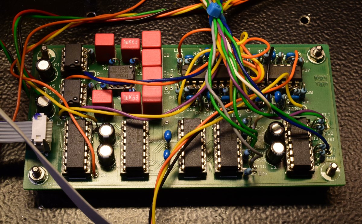
PGA board.
Download the schema in PDF, the board layout in PDF and / or the zipped Eagle files.
Relevant datasheets: OPA4134.pdf DRV134.pdf PGA2311.pdf
The PGA-board contains the volume control circuits and the drivers for headphone, line outputs and the differential drivers for the signals to the loudspeakers.
The stereo signals from the Selector boards enter on IC2, SLI and SRI. IC2 provides the channel dependent correction for the input sensitivities.
IC 5 does the volume control for the signals to the loudspeakers. These go trhough the rumble filters with IC1A,B ( 10 Hz, 3rd order) and the differential drivers IC3,4.
IC7 does the volume control for the headphone, the signals go out via the drivers IC9B,C.
IC8 and IC10 control the volume for surround effects. Currently I do not use these channels.
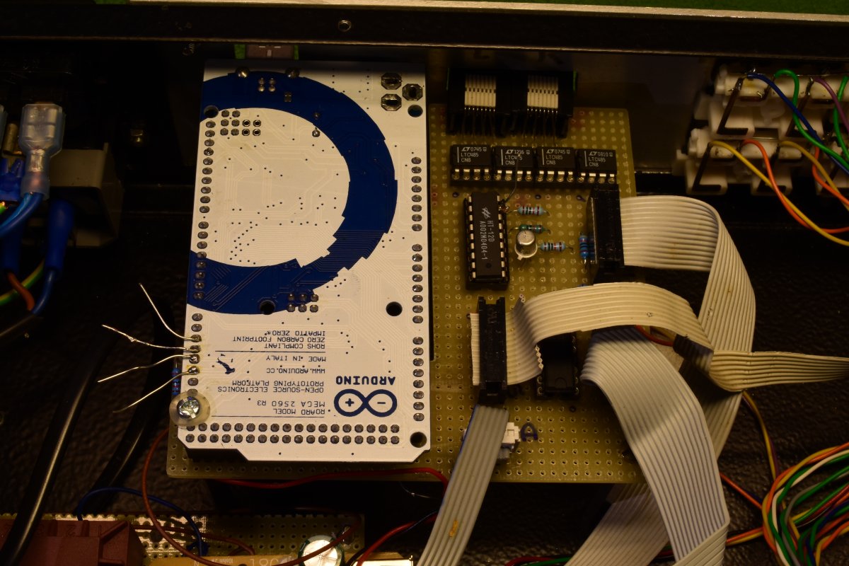
Arduino and interface shield.
Download the schema in PDF, the board layout in PDF and / or the zipped Eagle files.
Below the Arduino is an Ethernet shield, not visible in the picture.
The interface shield contains the RS422 drivers/receivers for communication with the loudspeakers (upper right), below that the IR decoder chip HT12D, and in between the cables the Nixie driver SN74141.
The board has not been routed, Only the components were placed to help handwiring the board.
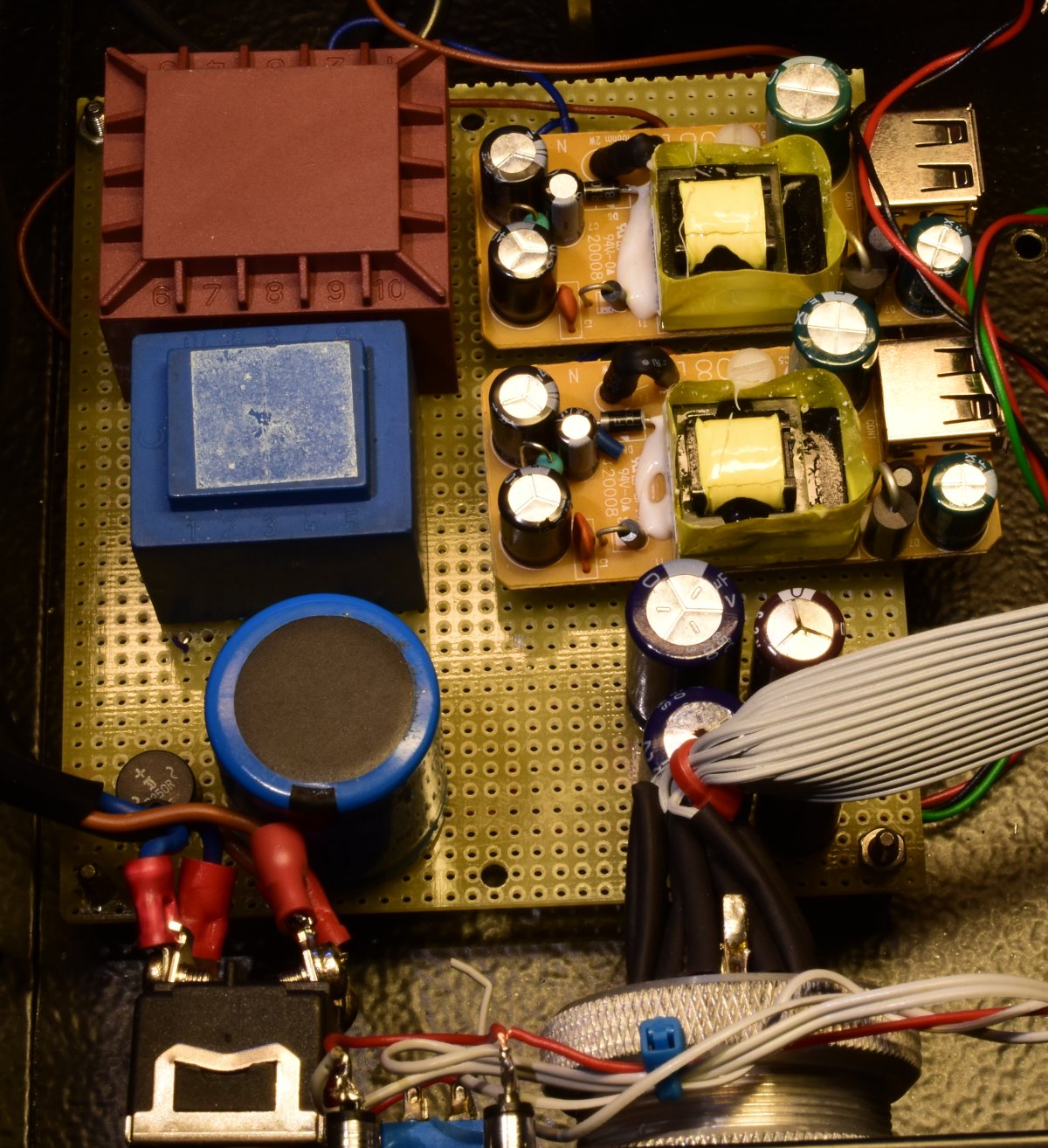
Power supply.
For the + and - 5 Volt I used the inner stuff of two Mains-USB adapters and some extra capacitors.
The high voltage for the Nixie tube is derived with two PCB transformers for mains separation.
There is no schematic made for this board.