Filter Board FLT
In brief:
The filterboard is more or less the heart of the system. It contains the crossover filter, the corrections for the loadspeaker's low-frequency drop and the level control circuits. Also it contains the Arduino microprocessor which monitors and controls several functions.
You may download the board's schematic in PDF and / or the zipped Eagle files. Note that the size of this board exceeds the free licence limits of Eagle. You can view it but you cannot modify the board without a licence.
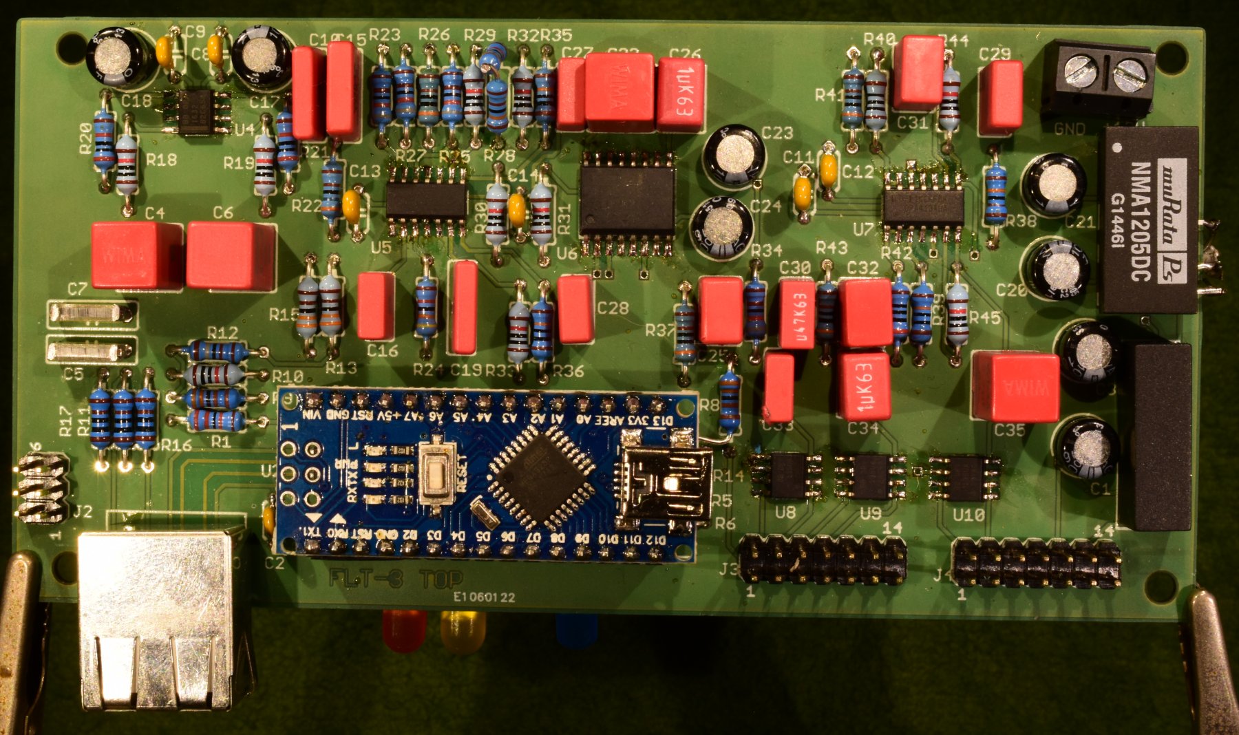
FLT board. (actually this is FLT-3 with some minor modifications, which are corrected in FLT-4 )
Before mounting I removed the screen of the RJ45 connector.
Description of the functionality: (pls. download the schema in PDF)
Audio.
The audio signal enters the board on the RJ45 connector J2 as a differential signal on pins 1 and 2. R16,17 and C7,11 reduce possible interference above 100 kHz. U6 is an amplifier with high common mode suppression, it helps in reducing audio frequent disturbances and effects of a possible ground loop.
U7A is the second-order lowpass filter for the Bass channel (145 Hz -3dB), U7D the second-order highpass filter for the Tweeter (1307 Hz -3dB). U7C is the subtraction stage and produces the Midrange signal.
The reason that U7D has gain is as follows. It turned out that the power amplifier for the tweeter was not happy with the high capacitive load of the electrostatic loudspeaker, approximately 6uF, so I put a 2 Ohm resistor in series with the step-up transformer. This gives a lowpass filter with 12 kHz -3dB so it had to be compensated for. This compensation is done with C25 and R36,39 on the FLT board and required compensation of the gain loss.
The signals for the Bass and Midrange channels go through U8, which is a 2-channel volume control with a range of -96 .. +31 dB in steps of 0.5 dB. Here the output levels of the Bass and Midrange speakers can be matched with the Tweeter.
U7B is the first-order low-up filter for the Bass channel, U9B is the anti-resonator together with the Gyrator U9A. For details refer to the Elektor article about the Time Correct Bass Reproducer.
The low-up filter for the midrange channel is combined with the subtractor U7C. U9C and the gyrator U9D are the anti-resonator.
U10,11,12 are the differential drivers to the power amplifiers.
At several locations DC blocking capacitors are present. The low-up and anti-resonator circuits have very high gain at DC and so will amplify offset voltages to unacceptable values when everything is DC-coupled.
All opamps and drivers used have extremely good distorsion specifications and are driven from relatively low impedance sources so the effect of the non-linear input capacitance is negligible. Important datasheets: OPA1632.pdf OPA4134.pdf DRV134.pdf PGA2311.pdf
Power switching.
On pin 6 of the RJ45 connector J2 a 5Volt signal CR+ enters the FLT-board. This signal turns on the solid-state relay on the Power Board and awakes the Arduino through D1. After a few seconds, when all power is ok the Arduino takes the Power Amplifiers out of reset, and the music can play.
Near the power board sits a neon indicator showing that mains power is available. In series with that neon bulb is an optocoupler which generates the MAINSOK signal, a 50 Hz square wave. When this signal does not change polarity in 15 ms or when the CR+ signal goes down, the Arduino brings the Power Amplifiers into reset mode.
The board is supplied with +12 Volt. On board DC/DC converters derive +5D for the digital circuits, +5A and -5A for the analogue cicuits.
With U3 a 2.5 volts precision reference voltage for the measurement of the supply voltages is derived.
For details of Communication, Error handling and Monitoring see the Software page and / or the Messages page.
Communication.
U4 converts the RS422 signals from/to the Control Amplifier to 5Volt levels acceptable for the Arduino.
Under normal listening conditions this communication is silent. The only digital activity outside the microprocessor are the slow blinking of the blue LED3 and the 50 Hz square wave MAINSOK from the Powerboard.
To adjust the output levels for the Mid and Bass channels a PC/Laptop program has to be started which talks to the Control Amplifier over the local area network. The Control Amplifier conveys the information to the FLT boards.
Error handling.
The TPA3255 in the power amplifiers can produce several types of errors (see the datasheet of TPA3255 for a complete overview).
The most important are:
Clipping.
If the output signal clips to GND or PVDD a series of low-pulses are generated on the line CLIP_OTW. In the software on the FLT board these events are counted in 2 ClipCounters, one for each TPA board. A change of one of these counters will trigger a message to the Control Amplifier where an error led will flash shortly. The ClipCounters are visible in the Configuration Tool when communication with the loudspeakers is established.
Overtemperature.
A chip temperature over 125 °C brings the line CLIP_OTW continously low. This condition will be sent to the Control Amplifier where the error led(s) will be flashing as long as this condition lasts. If the temperature lowers below 125 °C the error reporting stops automatically.
Fault.
This pin reports a multitude of error conditions. Some are latched, which means that the TPA must be reset, others disappear when the error disappears.
The software on the FLT board will send an error message to the Control Amplifier, bring the TPA in reset mode for a while and after that checks whether the error has gone. If not error messages are continued. The orange error led will be on as long as the error exists.
Monitoring.
The Arduino on the FLT monitors the supply voltages and the zero crossings of the mains voltage. If out of range or absent the blue led on the FLT will flash at a fast rate, the TPA will be reset, and error messages will be sent to the Control Amplifier where the error led(s) will flash at a fast rate. The voltages and the mains condition are visible in the Configuration Tool.
Note that if the mains voltage fails the Arduino on the FLT stays alive as long as the Control Amplifier provides the CR+ signal.
Cross Over.
Pspice simulation of the cross over. Green = Bass, Red = Tweeter, Cyan = Midrange, Yellow = sum(Bass, Midrange, Tweeter)
The -3dB frequencies are 145 Hz for the bass channel and 1307 Hz for the tweeter.
Below the pSpice model. Component numbering is according to the FLT-4 schema where relevant.
* 3 way subtractive Butterworth
* SallenKey topology
* Signal source
V 1 0 AC 1
* Simulation
.AC dec 150 10 100k
.PROBE
* Low pass
R24 1 12 3.6k
R26 12 13 43k
C20 12 14 220n
C21 13 0 33n
E7A 14 0 13 14 1E3
* output i node 14
* High pass
C18 1 22 33n
C19 22 23 6.8n
R25 22 24 8.2k
R27 23 0 8.2k
R28 25 0 3k
R29 24 25 8.2k
E7D 24 0 23 25 1E3
* output is node 24
* Inverter
R1 1 31 10k
R2 31 32 10k
E1 32 0 0 31 1E3
* output is node 32
* Subtractor
R30 24 33 37.3k
R31 32 33 10k
R32 14 33 10k
R34 33 34 10k
E7C 34 0 0 33 1E3
* output is node 34
* Summed output
R101 14 100 10k
R102 24 100 37.3k
R103 34 100 10k
R110 100 101 10k
E100 101 0 0 100 1E3
* output is node 101